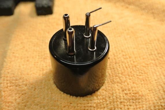
The Type 83 Tube was a 4-pin tube rectifier used in many device circuits. It had a low voltage drop of about 15V average and had Mercury vapor in the tube to regulate the voltage drop so it did not sag under load. This made it usefull for devices that needed a constant voltage under a range of load conditions.
The most common place we see these today are in Tube Testers like the Hickok series as well as teh B&K and others.
While other rectifier tubes in test equipment cannot be easily replaced due to the difficulty in replicating the proper voltage sag under load, the Type 83 tube is easily replaced with a regulated SS unit, usually with little to no effect on device calibration. To simulate heater load two 10 ohm resistors are used and the circuit is as follows-
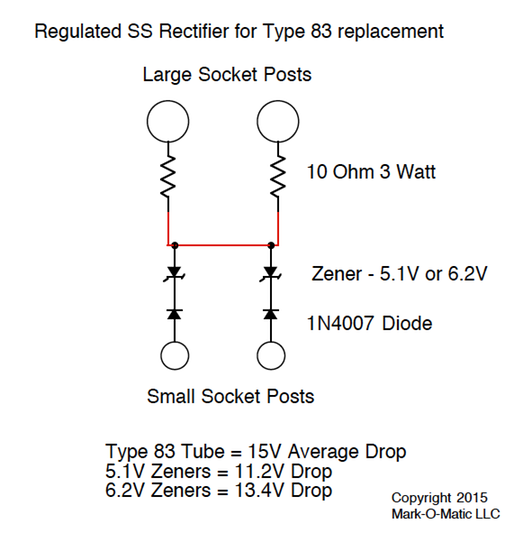
You can of course find Zener Diodes to provide any voltage drop you would like, but for Hickok Testers in particular I have found that the 13.4V works very nicely and povides some relief on the transformer of these old devices. For devices where the trasnformer is nearing end of life it may sometimes be neccesary to lower teh voltage drop even more to get the “line” adjustment to set properly. This is a good substitute for bringing into working condition a tester that otherwise would be called for transformer replacement.
In constructing your SS unit it is impoertant to note that for Diodes and particularly for Zener diodes, the heat dissipation happens mostly on the leads. So it is important to keep lead length long to allow for adequate heat dissipation. Using a potting compound will increase heat dissipation and lengthen the life of the unit. For very high current uses a heat sink can also be mounted in the heat conductive potting material - jut be carefull not to do so in a manner that will contact the leads.
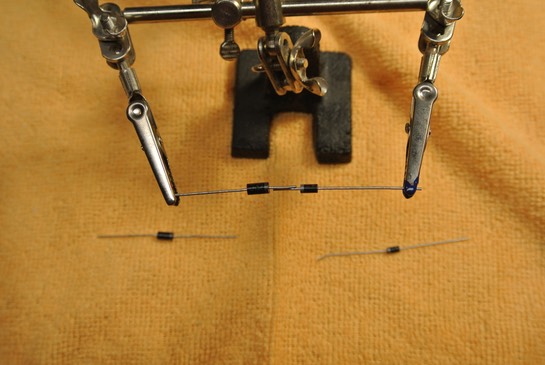
Step 1- Solder teh Zener to the Diode as shown in the schematic. The Line on the diode and zener devices should point TOWARDS each other.
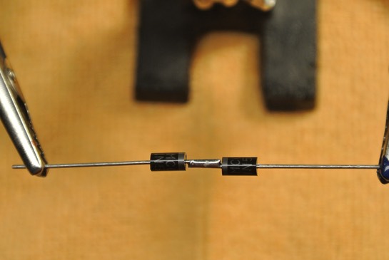
Step 2 - After Making a Pair Solder the pairs together as shown in teh schematic. The ends of the ZENER diodes get soldered together.
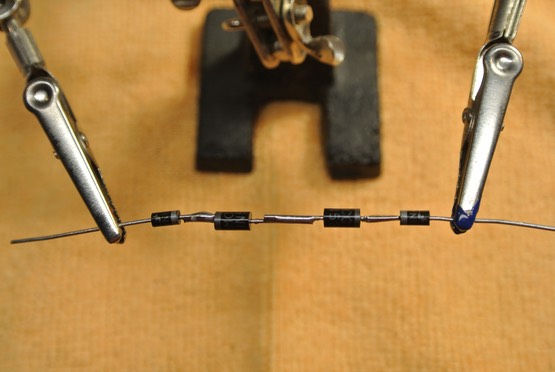
Step 3 - Fold the unit so the ends of the DIODE can fit into the SMALL pins on the 4-pin socket and solder in place.
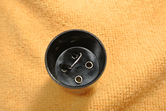
Step 5 - solder in place. The best was to solder socket pins is to dip the pins in solder but since almost no one has the equipment to do that you can solder them directly but its a bit tricky to get right. You need to ensure that you get solder to trickle or run into the pins.
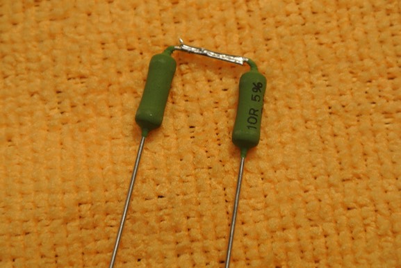
Step 6 - Solder two 10 ohm 3 watt resistors together. Fold as shown and insert into the LARGE pins of teh 4-pin socket and solder as you did with the diodes.
Step 7 - When all the componants have been soldered into the socket… then solder the two folded sections together in the middle.
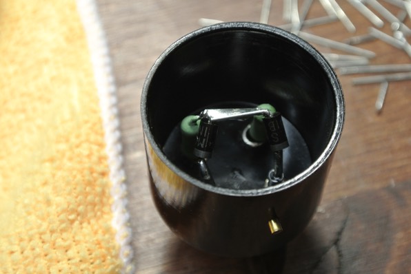
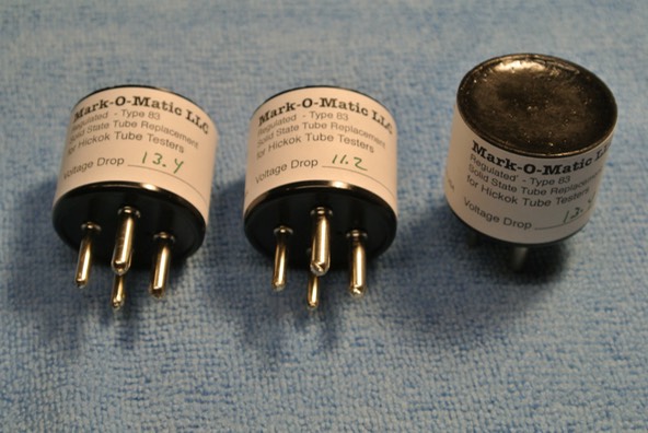
Step 8 - Fill with Potting Compound to allow good heat dissipation and protect components from fingers, and oxidation, etc. Label with the voltage drop you used.
I make batches of these for devices I work on and for other people, but I haven’t been able to keep up with demand. I’m happy to custom make you one if you have a need and not the skill, but for most dkilled DIY folks these instructions should suffice.
IMPORTANT - These SS units can be tested in a tube tester using a standard 83 tube roll chart setting. TEST EVERY UNIT ! Testing will ensure that you do not damage the device you intend to use it in.