V69 DIY Mod
Do It Yourself Instructions
The MXL V69 seems to be a very popular mic among low end enthusiasts. I listened to one once and initially wasn't very impressed, but over time thought that maybe the mic is worth a second look, at least from a modding perspective. Lots of people seem to have them, so it seems like a good opportunity to learn more about the design and possibly a few minor improvements that can be done by the average modder.
Lets dive right in. The V69 is a charge amp design. I admit I'm not an expert on valve charge amps, but the design is not overly complicated. Lets take a look at a textbook example.
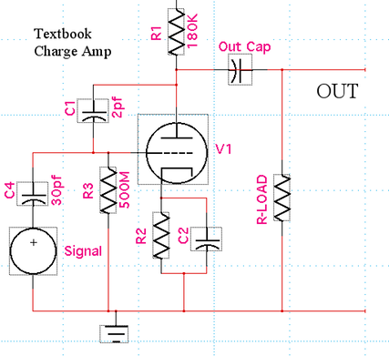
Without getting into the math (the uber geeks can use google or there is a small reference in Morgan Jones' "Valve Amplifiers" book 4th edition - page 102) at a very basic level what we have here is a feedback amplifier. The feedback is complete and not limited by a resistor, but only by the size of the capacitor. Because of the relationship between the feedback capacitor and the input capacitor ( C4 above ) - a smaller feedback capacitor will have a slightly greater gain, and a larger feedback capacitor will have a slightly less gain factor. Overall gain however will tend to hover right around unity. It's somewhat similar to a cathode follower in terms of output signal level and impedance - capable of driving relatively large loads.
A cathode follower, on the other hand, has very little effect on the actual sound or "tube-ness" of the sound and it's the tube-ness that people generally desire. So the charge amp is a way of having cathode follower like characteristics yet it has good noise rejection and has the tubey-ness that people desire.
On the other hand, because the gain is near unity, you will need to boost the signal additionally to reach the final output levels desired and the V69 is no exception as it employs a rather complicated FET/transistor based gain section following the tube.
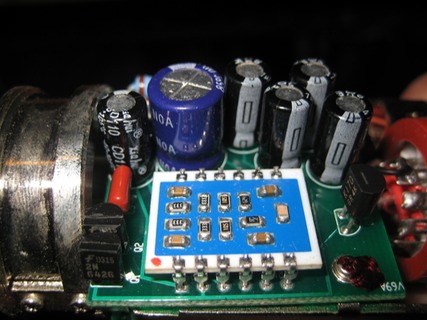
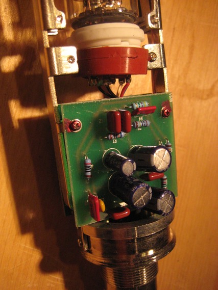
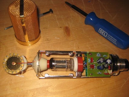
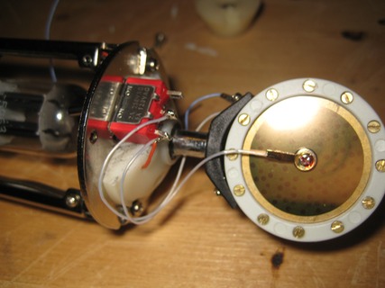
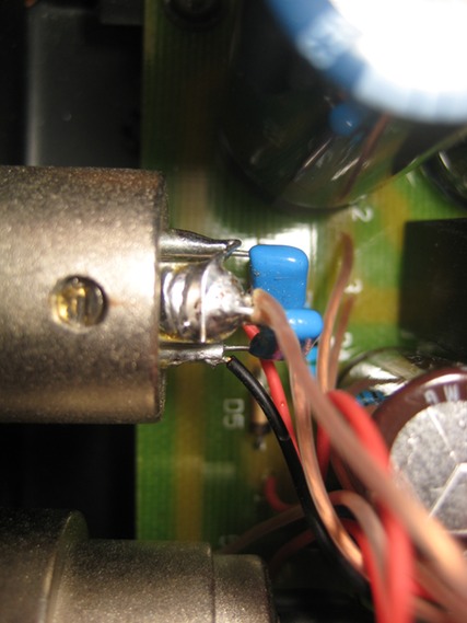
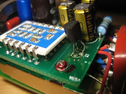
The V69 back side showing final gain stage.
REVELATION 1 - Since the tube stage, as a charge amplifier, is always near unity, the actual gain of the tube has relatively little effect on the circuit ! I've seen thread after thread about whether or not to use a 12AX7, 12AT7 or 6072 in a V69! Why spend upwards of $100 for hard to find 6072 NOS tubes when a $20 - $30 NOS 12AU7 will do the trick just as well? In my initial tests with various tubes I used a RCA 12AU7 clear top and the measured noise floor was LESS than a 6072!
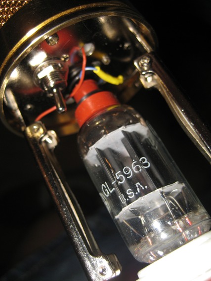
Additionally, given the voltage levels of this device, I see this as a perfect opportunity to use a 5963. A 5963 is a 12AU7 variant .. it's kind of like an opposite of a 5814 ( also a 12AU7 variant ). While the 5814 is designed to spend very little time in cutoff (you can actually damage the tube if long periods of cutoff are experienced by the tube, and some data sheets will warn against this,) the 5963 is designed TO spend long periods in cutoff, primarily for digital or other on/off circuitry. Due to this special behavior the max plate voltage is less, at 250V vs 300V and the heater to cathode max is less as well at 90V as opposed to 180v. These discrepancies have historically made the 5963 a somewhat unpopular tube for 12AU7 applications. However they are wonderful sounding tubes used in the right circuit. I have a personal stash of about 30 pristine NOS 5963's, many of them 1950's blackplates, and I only spent an average of $7-$20 each ! (hopefully this article will not create a run on 5963's and thus drive up the prices ! ssshhh ! )
http://tubedepot.com/nos-5963.html
http://tubedepot.com/nos-5963-jan.html
I have often wondered if the 5963 is truly a different design. I have tested them in circuits where the max voltage ratings for either plate or cathode to heater was exceeded and they seemed to perform just fine. Is it really a different tube, or does it simply meet the long cutoff time specs without damage at those rated voltage levels?
In any case - for this mic, use whatever 12AX variant you like, or whatever you have on hand. The mic will work with all of them. 12AX7, 12AT7, 12AY7, 12AU7 and the various naming conventions of those tubes.
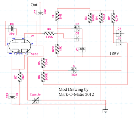
The Circuit - Lets take a look at the tube portion of the actual circuit. I drew this myself pretty quickly, it is not complete and may not be 100% accurate, but it's more than enough to let me know what's going on at the actual tube stage.
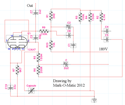
Rough V69 at the tube
So you can see right off that it's a charge amplifier but they have strapped the second triode in parallel.
What interests me most about this from a modding perspective is -
C7 - the output capacitor that feeds the silicon based amplifier circuit.
C3 - the feedback capacitor
C19 - the cathode bypass capacitor.
Changing these 3 capacitors to something of better quality will have the greatest effect on the tube portion of the circuit.
For C7 - I'd love to find a way to squeeze a film cap in there, but room is scarce so I opted this round to simply upgrade the electrolytic quality. If someone finds a way to squeeze a film cap in this location, let me know and I'll update the info here.
For C3 i think a polystyrene would sound best, but I had trouble finding one of the right value. I opted for a silver mica at 39pf.
For C19 - this is a big cap so will definitely need to be electrolytic. I opted for a 47u replacement over the 22u to help boost low end. Since the mic does not have a low end rolloff, if you're into that or find you often use a rolloff switch, then you may want to stick with 22u. Going to 47u should improve frequency response around the 100Hz area for this circuit.
MOD - So that's our starting mod.
1. Replace C7 with a high quality 2.2u 250V cap (film if you can fit - SEE UPDATE 1 at end of article)
2. Replace C3 with a polystyrene or a silver mica 39pf - solder direct to tube pins 6 and 7
3. replace C19 with a 47u 25V - 50V high quality electrolytic cap
Mod
SOURCING PARTS - Sourcing parts can be a big pain. It's also no fun to need a $.50 part and have to pay $10 shipping for it. So I tend to let stuff I need build up and do the best I can to get as many parts from one source as possible. In this case I was able to get some Nichion and some Panasonic caps. I've never used Panisonic caps before so I thought this a good opportunity. I could not find the better FC caps, but did manage to get M series. The photos make all the blue caps looks somewhat the same but the Panasonic are a strikingly pretty blue, almost like a lacquer with light blue letters, and also a red lettering that is so small I cant seem to read it. Time is precious and I'd much rather pay a little more and get stuff faster from an easier to use/browse site like Antique Audio, or Parts Connexion, but they don't always have what I need. Ordering from places like Mouser, Digikey, Newark .. they have a lot of selection but it's sometimes overwhelming to the point where I've started saving part numbers and links in a spreadsheet like they were golden. In any case, I figured whatever I have with the Panasonic is better than what came stock in the mic.
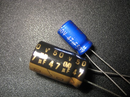
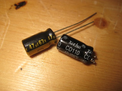
Nichion Muse and Panasonic M series caps of the same value.
Bigger is usually better in terms of caps. I have two V69 mics at my disposal so I decided to use the Panasonic for the first mic, and I'll use the Nichion on the second mic.
I have been toying with the idea of using a PC board film cap sandwiched between the two mic circuit boards. A 1uf cap is just the right size, but any bigger and it just won't fit. So I may try switching to a 1u cap for C7 in the future to see how the circuit reacts. Is the presence of film at that location enough to offset possible effects of the smaller value cap?
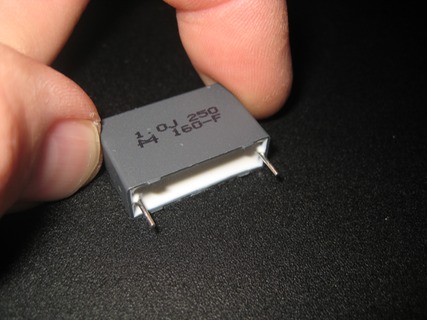
a 1uf Film Cap that might be able to be sandwiched between the mic's circuit boards
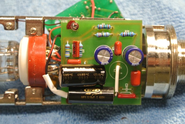
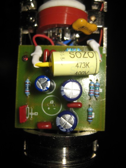
FRONT BOARD
The tube circuit side of the V69
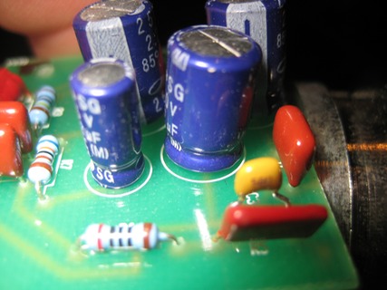
The yellow cap in this photo is C3 and the two blue caps closest are C19 on the left and C7 on the right. These are our targets for removal.
MOD TIP - Always take lots of pictures! in this case the back of the circuit board has many small wires and the likelihood of one or more popping off during work is high, particularly if you don't have schematics. If you don't know where to put the wire back, it can make a simple Mod quite challenging!!
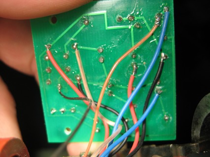
Back of the tube circuit board
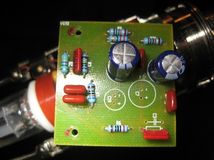
Target Caps removed
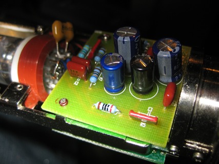
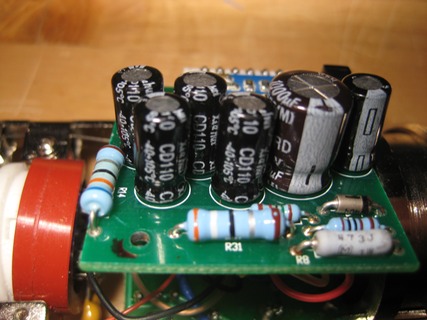
Panasonic replacement caps installed
The 2.2u 200V cap is another Panasonic variant I know little about, but again I figured it was better than what was in there and was what was available and wasn't overly large. The curve of the mic cover is not very far off from these component tops. As I experiment with caps down the road, if I find anything remarkable, I will update this page.
Note I did not place the feedback cap C3 back onto the board here, but rather moved it to the tube pins.
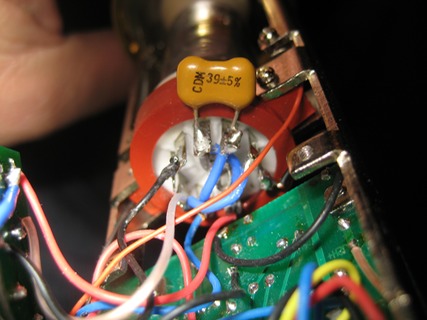
Silver Mica installed on tube pins
For the feedback cap C3, since the tube was strapped in parallel, it gave me an opportunity to use the second triode tube pins to directly accommodate the much larger cap size. Solder to pins 6 and 7. When looking at the bottom of the tube directly at the pins, the pins count clockwise. 1 on the bottom left around to 9 on the bottom right. Pin 9 can also be identified by the black wire going to ground as it is the heater ground.
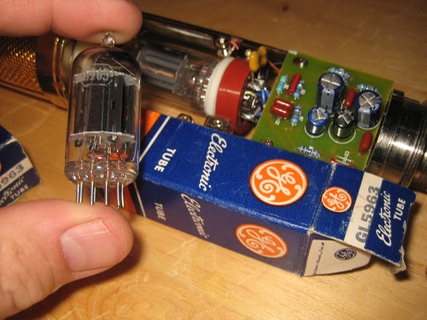
a NOS 5963 to replace the used RCA clear top 12AU7 I was testing
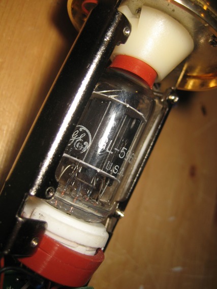
Installed and ready to go
TESTING AT THIS STAGE - Clips or it didn't happen, right?
I fully expected the differences at this stage to be quite subtle. In many cases, particularly with vocals, the effects of a small change may not be immediately apparent, however when you get the track into a mix you suddenly notice a larger difference in how the mix is coming together. Identifying those parameters from a single source recording can be difficult to impossible at times. What I have recently discovered is that for doing quick tests, using distorted guitar as a source will usually bring out some of the nuances of a small change in a slightly exaggerated manner making it easier for the ear to detect. Distorted guitar is a very complex sound, and somehow this seems to do the trick, at least for me. So for this first test, that was my focus. I wanted to see what the cap change might have done BEFORE I swapped out the capsule.
TECH NOTE - I no longer own any pres that are not tube based, nor do I own any rack pres that haven't been modded or tweaked by me somehow. Since I didn't want to color the sound, my only option was to use inputs 1 and 2 on my Digi 003. Not the best pres, but they will suffice for this test and should be somewhat transparent compared to my other choices, even if of lower quality.
SURPRISE ! - I was immediately surprised to find that the mod provided a gain boost ! Now a boost in gain is not always a good thing, and particularly in tube mics the tube is often swapped out with a lower gain unit to provide more headroom for something like a transformer. But in this case there is no transformer, so as long as the silicone stages can handle it, thats just free gain as far as I'm concerned. A transistor will generally distort at its peak in an obvious and immediate manner, and I have not detected this so far in my test. Measured SPL for these first clips at the source point was 98.8db.
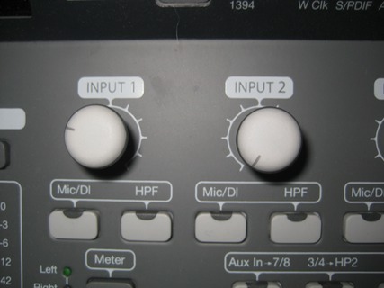
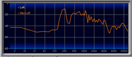
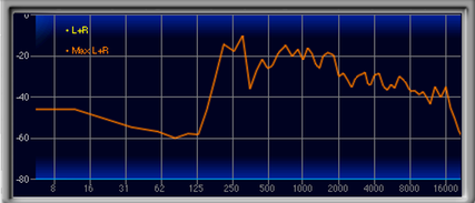
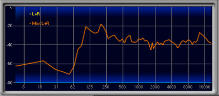
Mic settings when gain is matched in Pro Tools. Left is original , right is the mod
The right setting is just above min, though the photo seems to show all the way down.
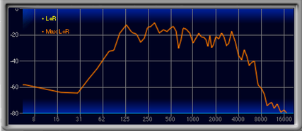
Dist Guitar Clip 1 - Stock Mic. http://www.mark-o-matic.com/media/cap-cab-orig.wav
Dist Guitar Clip 2 - Recapped Mic. http://www.mark-o-matic.com/media/cap-cab.wav
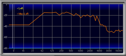
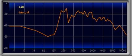
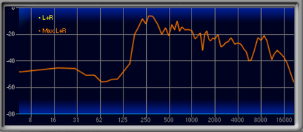
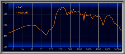
Notice the reduced HF around 8K in the recapped version, but a slight boost at 4-5K. Interesting results. Overall the two clips LOOK similar but the sound is different.
My conclusion? I can't decide if the recapped mic sounds clearer, or if it's simply more scooped than the original. In any case I do like what I'm hearing with the cap swap. Burn in time was only about an hour at this point. I will give these much more time to settle in before doing the Capsule tests.
CAPSULE SWAP to a K47 TYPE -
For this particular mod I decided to go with RK47 from microphone-parts. This was my first time using them and I have to say the turnaround was blazing fast and they had good communication.
Link - http://microphone-parts.com/rk47-microphone-capsule/
They also have an excellent capsule install guide here Link - http://microphone-parts.com/capsule-installation/
I want to put in a switch for Omni operation, so we will focus on that and not the step by step capsule.
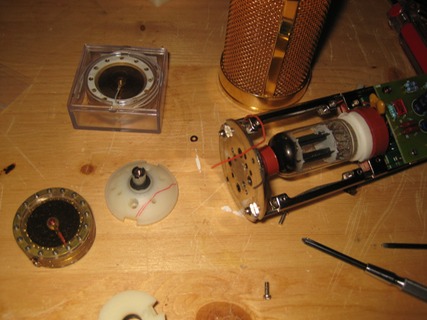
Remove the old capsule and keep the old wire length as long as possible. Clip them up next to the old capsule. At some point they changed the design of the V69 and the tube is up by the capsule now, meaning the capsule wires are REALLY LONG. Given that connection is the most sensitive in the entire circuit, I'm not sure that was a smart move, but I'm sure they had their reasons.
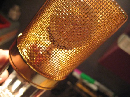
Remove the headbasket to gain access to the capsule.
headbasket removed
Remove the capsule mount entirely.
On the BACK side of the capsule area on the base of the saddle mount we are going to cut the base off to accommodate a switch.
Red line indicates approximate area of cut.
Use a Dremel or similar tool to remove the base area in order to fit the switch in place. You will need to go all the way into the black rubber in some places.
Be careful NOT to remove the portion where the screw holds the base to the plate.
Remove the plate and use a 1/4" bit to widen the hole in the appropriate place for the switch.
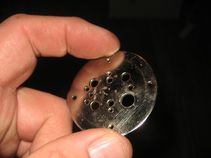
Plate showing enlarged hole ready for switch.
Install the switch and reassemble.
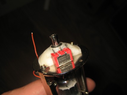
Plate and base reinstalled with switch.
When the mic is finished, I should be able to simply screw open the mic base and select Cardioid or Omni pattern.
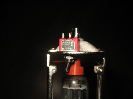
Side view showing switch
Solder the red wire that was connected to the center of the old capsule to the same side (front of mic) center wire from the new capsule. These two wires will be soldered to one of the switch terminals on the edge. The center switch terminal will be connected to the other (back side) capsule wire.
WARNING !! - hot soldering iron + mylar = melted capsule.
I used the capsule case cover gently placed on the top while I was working.
Soldering the wires and protecting the mylar on the capsule
Here's a finished shot. I was being very cautious about the heat to the mylar and I ended up making cold solder joints here. The mic is VERY sensitive so any cold solder joints, even though they may tone out, will not work. I spent a bit of time troubleshooting when I was done.
Switch all wired up
MODDERS TIP - Not only are mics very sensitive to cold solder joints, but the headbasket acts as a faraday cage (see - http://en.wikipedia.org/wiki/Faraday_cage) AND on some mics (this is one) the base also works as a faraday cage. If these cages are not in place the mic wont work correctly, or in some cases will not work at all So you CAN'T test with the headbasket off. I know it's a pain, but you really do have to put it all back together, test and then rip it all back apart if there is a problem or if you need to change something. With tube mics it's also a good idea to avoid having the approximate 200V exposed as well. Safety first!
Once its all soldered up, reassemble the mic. Be sure NOT to crush any of the delicate wires! I also chose to remove the inner layer of mesh from the headbasket for this mod.
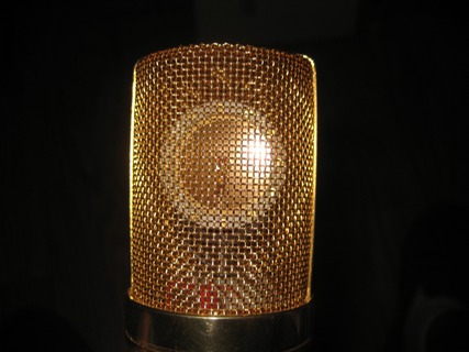
headbasket without inner mesh layer
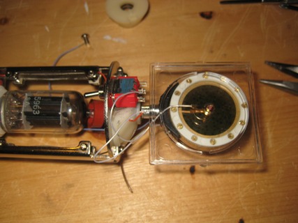
Another view to show the switch inside
And there we have it. The Omni switch works nicely (once I had troubleshot the cold solder joints on the switch I mentioned earlier.)
There is a white piece of plastic that helps hold the tube in place. That will also need to be trimmed if you still want to use it. I opted to remove the spring from the white piece and extend it a little bit. Snapped onto the orange section and pressed directly up against the plate, this appears to hold the tube in place just as well. To keep the spring from sliding around I ended up putting a small sticker on the slick metal plate to give it more friction (not shown.)
Switch access from inside the mic Note the proper use of heat-shrink tubing on the connected wires as opposed to electrical tape.
If you don't have a heat gun for the smaller heat shrink tubing you can gently rub the upper (and cooler) portion of the soldering iron gently against the material.
CHECKPOINT - How does it sound?
With the new capsule in place I really was expecting to hear a pronounced difference. I did not. Well maybe a little bit in the high end which was more controlled on the K47 capsule. Certainly not what I was expecting, and not much difference from my initial caps only tests. Not enough in my mind to justify the capsule swap for a typical low ender.
REVELATION 2 - Unless you intend to do the full mod in this article, a simple capsule/tube swap will probably yield minimal results for the average low ender. Higher end preamps will reveal more of a difference however.
Judge for yourself -
Female Vocals Clip 1- Stock Mic. http://www.mark-o-matic.com/media/fv-2-orig.wav
Female Vocals Clip 2 - K47 Capsule. http://www.mark-o-matic.com/media/fv-2-k47.wav
I did not believe these results at first. I must have done something wrong. Right?
I checked and rechecked. I even tried a few other pres and also pres that had their own converters so I wasn't using the 003's converters. I could certainly hear a bigger difference with the better pres but overall it was still not remarkable. I had invested considerable time at this point, there must be an ultimate solution.
Follow the Signal - So I do know that after we have tweaked the tube end of things that the resultant signal goes into an output amplifier on the other side of the mic. I was really hoping this was going to be quick and easy, but apparently not. A little reverse engineering on the back side is going to be necessary.
I didn't want to draw a schematic for the back side at this point, let's go for the low hanging fruit and see if that helps. The output stage consists of one FET (K170 Toshiba low noise FET) and two 2N6426 (high gain darlington NPN.) Certainly candidates for a swap out and swapping the FET is pretty typical. If the FET needs rebiasing though that means dealing with the surface mount resistors - probably not for the average modder. We will skip this for now.
My next concern is caps and resistors along the signal path. I can't really do anything (that I know of, or that would be easy) about the surface mount resistors on the special blue colored board that completes the FET & transistor circuits. However, there are other caps in or along the signal path as the signal exits the mic and goes to the PS and on to the pre.
Since I did significantly less reverse engineering on this side of the PCB, I'm going to use the shotgun approach.
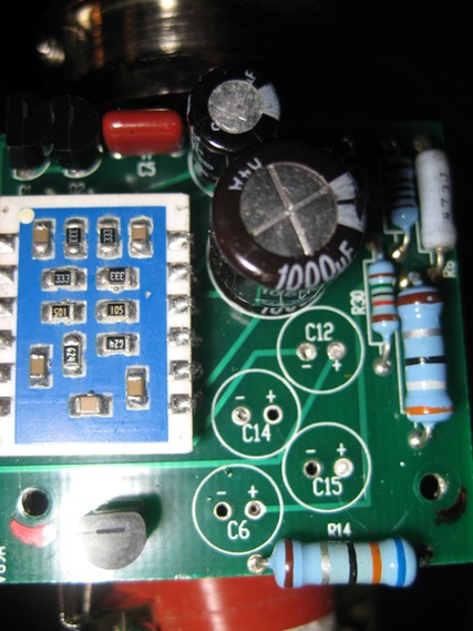
Target Caps. The set to the left of the large cap we want to change the center two at a minimum (C14 and C15), however I'm going to change all four.
We also want to change the one on the right of the large cap, which is the final output cap.
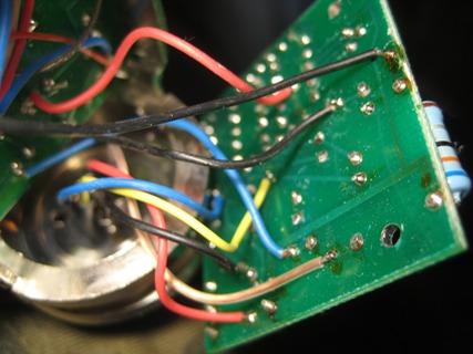
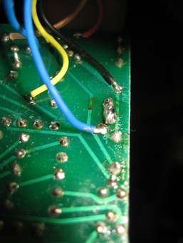
Backside of this PCB. The blue wire to the very left ( almost out of view on the PCB ) is the output.
Yellow wire is the other side of the balanced signal. On the power supply the yellow wire is shorted to the case as well - not really a true balanced circuit.
For the set of four, I'm going to use Nichion. New and old caps shown here.
Targeted four caps removed.
I used another panasonic for the output cap but forgot to get a photo of the removed cap in that position. Oopps, sorry.
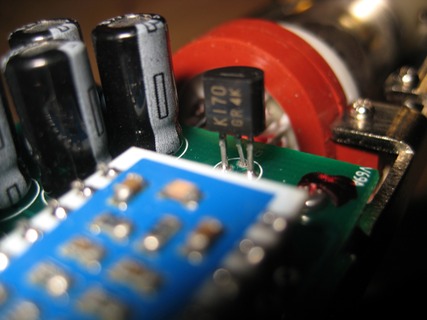
The FET is the lower chip here and the NPNs are up at top left next to C5.
C5 at the top is a 10n film cap, but since its not electrolytic and I don't happen to have a better 10n on hand, I'm going to leave that as is. It could be a coupling cap, or it could be in parallel with the large output cap. A possible follow up item.
My assumption is that the 1000u big cap is power smoothing, or at least that's what I would be doing with that cap, so Im leaving that as is too.
Caps in place.
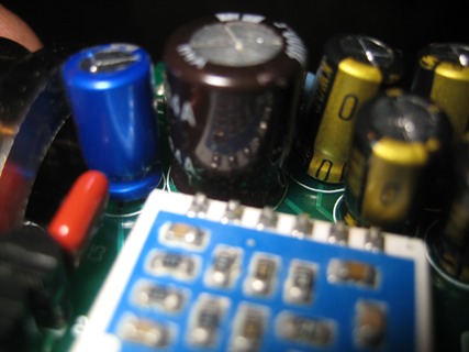
POWER SUPPLY - Now let's take a look at the power supply.
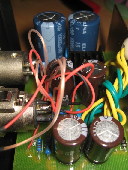
What do we have here? Decent Elna Caps? Too bad there were no Elnas in the signal path.
On the output connector I discovered two caps. One shunts the positive signal to ground and the other shunts the positive to negative. The negative lead is tied to ground as well so that doesn't make much sense, and feels like some last minute Mickey mouse bandaid. My assumption at first was that these were for radio frequencies. However I measured them at 50n. If we assume a worse case scenario of 600 ohms output impedance that puts the rolloff frequency at about 10K. If we assume 200 ohms output impedance as the spec sheet indicates that puts it at 16K, still well into the audible range. Were they trying to tame the high end Chinese capsule sizzle?
Two 50n caps on the output connector that need to go.
If I have problems with radio frequencies, I might try a 10n or maybe even go to a 500p or smaller to start with, but for now I'm just going to clip these.
FINAL MOD CLIPS!
OK, now we are getting somewhere. I found it slightly harder to set the levels because the mics were not reacting the same to changes in frequency as the vocalist sang.
To me, the mod now sounds a little bit clearer with more dynamic range, making the original mic sound somewhat less exciting and dull by comparison. At least to my ears. Still it's not the dramatic change I was expecting from all these parts getting upgrades. The vocalist liked the original mic better and claimed it has more of the old 50's lo-fi kind of sound. Well I guess if I was going for 50's I'd use a ribbon mic, but just goes to show how subjective these things can be.
Female Vocals Clip 1 - Stock Mic - http://www.mark-o-matic.com/media/fv-6-orig.wav
Female Vocals Clip 2 - Modded Mic - http://www.mark-o-matic.com/media/fv-6-mods.wav
Guitar Cabs - I think this mic really excels on guitar cabs. These are my favorite clips with this mic.
TECH NOTE - This is an Egnater Tourmaster. The clip goes through each of the 4 available channels. The guitar is a Fleck.
Cab - Clip 1 - Stock Mic - http://www.mark-o-matic.com/media/LouCabs-orig.wav
Cab - Clip 2 - Modded Mic - http://www.mark-o-matic.com/media/LouCabs-mods.wav
What about the OMNI switch?
Since the original mic does not have Omni capability, I decided to go head to head with the the C12 clone I built from the other DIY article. To this day that is still my overall favorite mic in my locker. At this point the modded V69 has about 20hrs of burn in on it, but the C12 has well over 100 I'll bet. It's not really a fair test since a K47 capsule should sound completely different than a C12 capsule. But it should be interesting all the same.
We will be sampling some drums. The room is small but decently treated and has traps and some foam, but also several diffuser panels on one end, making one end of the room a bit "live" while the other is a bit "dead" .. This allows me to move stuff around in the room and generally get what I'm looking for. in this setup the drums are on the live end of the room and the mics are as close to center of the room as I could get them. We won't hear a huge amount of reflections from the back side of the room (since that is the "dead end".)
Tech Note - End of a session and drummer had been playing on and off for several hours - so he was a bit pooped. Set is your average Gretch Catalina with Zildjian Cymbals. Snare is a 13x7 PDP.
Drum Room - V69 - http://www.mark-o-matic.com/media/DrumRoom-V69.wav
Drum Room - C12 - http://www.mark-o-matic.com/media/DrumRoom-C12.wav
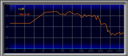
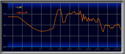
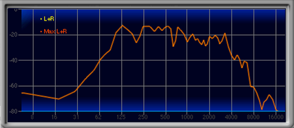
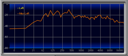
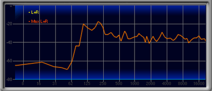
That is pretty darn flat looking
WOW what a difference. Even though I know the K47 capsule will be more tame in the highs, this comparison really brings out the level of quality between each mic. That said I spent probably $500+ to build the C12 mic and I've got about half of that into the V69.
Initial Conclusion on the V69 Mod ? After a lot of work (by comparison, the C12 was an easier mod I think) , the mic does sound better but it isn't night and day drastic like the C12 mod. I believe the FET/Transistor stage of the device is holding back what could be a really great mic. I have ordered some J309's and will give swapping that out a try. I've compared data sheets already and its possible the existing FET is biased in a region that could allow the J309 to be dropped in, but I'm not going to hold my breath, and expect a bias tweak to be needed. If that fails to improve sound quality to my liking, I may just rip out the transistor stage altogether and simply build a tube mic from the ground up. Stay tuned.
Mark
UPDATE 1 -
I was thinking about how to fit a large film cap into the mic and I realized that I have been considering the sections individually but not the sum of all parts together. A charge amp has a relatively low output impedance (much lower than Ra) and a FET has a relatively high input impedance. A 2.2u output cap on a final tube stage is common, but this is not the case in the V69 circuit as that particular cap is simply an interstage coupling device. The value MXL used as a coupling cap for C7 at 2.2u led me astray, as I feel that is a ridiculously large value in that location, and a much smaller value will do nicely without sacrificing low end, and probably fit physically. I decided to try a .047u which is many times smaller than what came stock with the mic. I also just happened to have a few extra of that value from working on an old Ampeg guitar amp.
if you look at the schematic you can see that the coupling cap connects at one end to R9 as well as Pin1 on the tube. So I ran a wire to the correct end of R9 (closest to the screws that hold the board in place) and connected the other end of the wire to the cap and also to the wire from Pin1 of the tube to the same end of the cap.
There is a red wire that runs between PC boards where C7 connects up. This is the wire that connects the C7 cap to the grid of the JFET. Disconnect this wire and connect it to the other end of the cap. Use heat-shrink to protect the leads from bumping into things.
The .047u (47n) Sozo fits nicely near the end of the board but also fits nicely near the silver mica cap on the tube pins. You will need to use some double sided tape or such to hold it in place so it doesn't move around when putting the cover on.
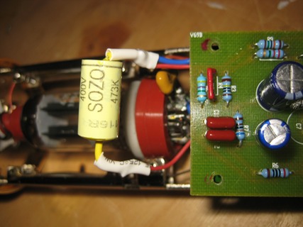
The .047u film cap wired in place of C7
just fits on the PC board with room to mount the cover.
How does it sound ? Sozo's take a really long time to burn in (up to 100hrs), but I gave it about an hour before trying it out. My immediate conclusion was that C7 is a critical cap in this design, and having a film cap in that location changes the characteristics of the mic in a very positive manner. So much so that I suspect simply changing that cap and nothing else will probably have a beneficial result. When I build the second unit, I will change that out first and test.
The mic now sounds much more like what I'd expect a K47 mic to sound like. There is a mellow smoothness now, and the cap has not even burned in yet!
Clip1 - Female Vocals - stock http://mark-o-matic.com/media/up2-fv-o.wav
Clip2 - Female Vocals - mods + Film Cap at C7 http://mark-o-matic.com/media/up2-fv-f.wav
While I had the board off I also looked at the FET connections and discovered that the FET does not actually connect directly to the special surface mount resistor board. But there are additional 1/4 or 1/8 watt resistors hiding under that board and they appear to be biasing the FET. So it may be possible to simply pop off the blue colored board to get to the components underneath. Stay tuned.
Mark
UPDATE 2 -
PART 1 -
Lets talk about FETs for a second. I have seen a lot of praise for the K170, which comes stock in the mic. The main complaint is that the Chinese don't seem to bias these correctly. I have also seen a lot more praise for the J305. However the J305 has been considered obsolete by the manufacturer and its hard to say, "use a J305" when you cant just go out and buy one, they are no longer available, or very hard to find. The J309, and more recently the J310 are the replacements. The specs look slightly better however use higher Vds voltages. But specs are not the whole story and its possible to have one device with high specs underperform a device with lower specs depending on the application. Technically the K170 appears to have a very linear and low noise floor, but I've often seen the J305 mentioned as an improvement. The J309, 310 have improved noise specs as well, but again depending on application may or may not be better. Since I don't have much experience with any of these, I'll just state they are different.
Because of the blue surface mount board in this mic, I venture to say that most people are not going to be into ripping that out and re-biasing, weather to rebias the K170 or to bias a new J305. The biasing resistors are underneath that blue PC board. However a simple FET swap is much easier, and may be doable by most people. The J309 happens to be within specs for the biasing currently on the unit with no modification. UPDATE 2014 - I have since the original article done a couple of drop-in of a J305. They also work very well as a drop in replacement if you can find them. However some brands have different PIN wiring than the original J305 so watch for that.
So for this first part of this update we will swap out the K170 FET for a J309 FET
The original K170 FET
I measured the stock bias specs at a Drain to Source voltage of 16V. The J309 will operate up to 25V Vds with the spec sheet listing 10V as average operating voltage. So Vds and Vgs ended up being not out of spec for the J309 FET and I knew I wouldn't fry anything even if its not 100% optimal in the load line. I decided to just drop it in and see how it did.
If you would like to try this - remove the old FET and replace with a J309. The J309 pinout is different. You will need to flip the flat side to the other end and do some careful re-pathing of the leads. here is a pinout diagram.
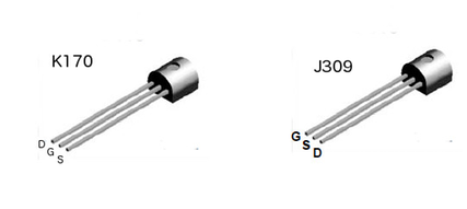
K170 and J309 pinout
J309 in place. A little hard to see but the pins on the right are reversed in the holes. The flat side now points towards the tube.
Results ? Im not going o post clips here as the difference is very subtle, and I had to do a lot of different tests to figure out what I was hearing. To my ears, and I can't quite put my finger on it, but the soundstage is somehow different, its like a different 3D spaciousness. Not better or worse to me, just different.
PART 2 - For the second part of this update we are going to get rid of the electrolytic output cap. After replacing the coupling cap and hearing the improvement I was convinced the output electrolytic needed to go. No room in the mic for a larger cap, what to do ?
Luckily this particular mic has a power supply, and maybe there is some room in there ? I decided to bypass the electrolytic cap altogether, and place a large film cap inside the power supply. Note that this will mean this particular mic will be married to the power supply, and if you have more than one care will be need to be taken to ensure they don't get mixed up.
C13, the output cap is the one on the left. Remove and bypass.
C13 is now bypassed. It looks like a blob of solder but there is actually a tiny silver wire in there.
I was uncertain what effect this may have. We are running multiple DC voltages through the cable TO the mic, why not run one DC line BACK with the signal and place the output cap in the power supply ? Not much more room , but enough to fit a 4.7U film cap in there, which I also bypassed with a 100n.
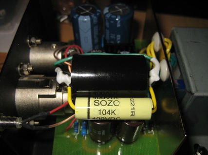
Cut the output signal wire going to PIN 2 - the right pin on the XLR as you are looking at the connector from outside of the supply. (the black one on my power supply) and insert a 4.7U and a .1u (100n) cap in parallel (or value(s) of your choice) inside the power supply. The stock cap was a 2.2u if you'd prefer to stick with that value. They sat nicely for me between the power filtering caps. Reminder again that doing this will marry your mic to the power supply, you wont be able to swap around unless the other mic/supply has the same mod.
Results ? Someone mentioned recording an acoustic with the V69 so I got my low end Martin out. Note, Im not a guitar player by trade, though I do use one to write, so I'm playing badly and these strings are probably a year old, but should be revealing in any case. Chorus from Any More.
Acoustic - Stock - http://www.mark-o-matic.com/media/Acoustic-all-stock.wav
Acoustic - mods http://www.mark-o-matic.com/media/Acoustic-all-mods.wav
At this point Im starting to be pretty darn happy with how the modded mic is sounding.
Conclusions ? In my opinion - I think the single most important thing you can do to this mic is get rid of the electrolytics in the signal path by any means available. Mods I did here are probably not the only valid methods. Do the signal caps FIRST. That is C7 on the tube board, and C13 on the FET board. Its more important than a tube swap, more important than a capsule swap. Once the signal path is clear you can start adding other mods as you chose and actually HEAR a significant difference with what you are altering.
Mark
UPDATE 3 - Oct 2014
I’ve done quite a few of these now. My first attempts I thought they were pretty good upgrades but not as spectacular of an improvement as the C12 mod. Buyers were very pleased with the few I sold however. Then I did one for a guy named Anthony and it turned out incredible. Stock Capsule. GE 5963 tube. Elna Tonerex on the cathode and an Erse as a coupleing cap. J305 FET. He called it his “Neve47".
So this has made me rethink this as a mod as a more serious mic possibility. I got a core recently to build another one just like Anthony’s - and turns out this new unit I got has the other sytle of PCB inside (The Large full-length PCB). So as soon as I can get to it I will update this page for the other PCB style.
Heres a photo of the Tonerex/Erse layout.